
The topic of measuring bifocal add powers is a common source of confusion in the industry. This is because the correct method of lens placement for this procedure seems counterintuitive. The correct method to determine the add power requires that the lens be positioned "backwards" from how one would measure the same lens for determining the distance power Rx.
When using the term "traditional bifocals" in this article, I am referring to bifocal designs where the addition power is on the front surface of the lens. Excluding modern Free-form bifocal/progressive lenses, traditional front surface designs are by far the most common design type.
This article will provide the reasoning behind this practice, and also provide data showing potential errors that result if this procedure is not followed.
Description of the correct measurement method:
The universally accepted method to correctly measure add power is to place the segment surface against the focimeter support, which requires turning the lens around for this procedure.
ANSI Z80.1 (and all other National and International standards including ISO) describes essentially the same method. ANSI Z80.1 -2010 (and all earlier versions) states:
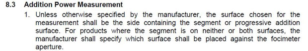
This means that for our traditional bifocal (where the segment is on the front), the add power will be calculated from measurements made when the lens is reversed from the position used for determining the measured distance power.
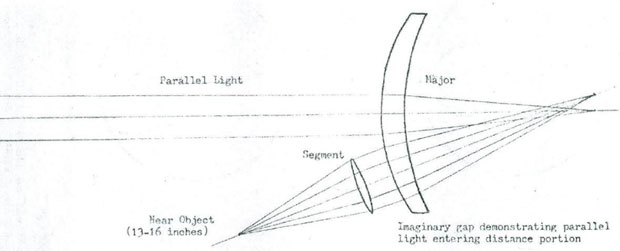
A nice illustration of this is shown below. It was copied from an old German DIN standard. In this image, the middle illustration shows how one should position the lens on the focimeter nose for determining the distance power but not the addition. Note that for this measurement, parallel light is entering the front convex surface (as it would from a distant object). This is important when explaining the "why" for measuring addition power.
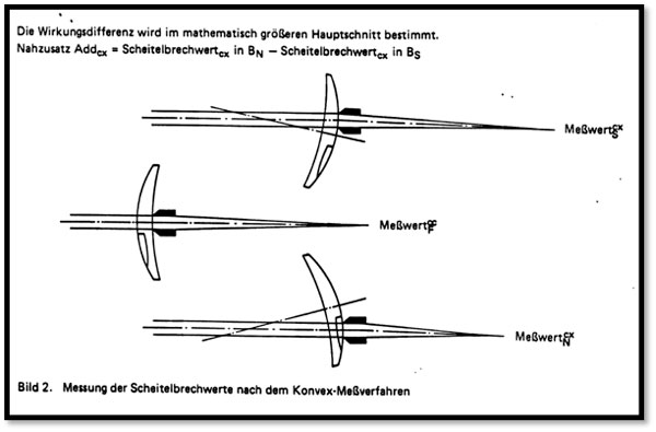
Turning our attention to the top and bottom portions of the illustration, you will see that two measurements are made with the lens turned around; these two measurements are both needed to determine the bifocal add. The top illustration shows the distance add power measurement point and the bottom demonstrates the near add power measurement location. Of course the add is the difference between these two measurements (Near – Distance).
Note that like our middle illustration, parallel light is entering the lens on the surface opposite the focimeter nosepiece for the addition power readings. This condition is achieved on the focimeter by reversing the lens. This is key to why this is done.
The next illustration is a schematic of the AO Lensometer, and applies to the basic principle used in most focimeters in use today. Note the Lensometer (AO Trade name for focimeter) was designed such that parallel rays of light are in front of the lens at the surface opposite the nose, just like in our DIN illustration.
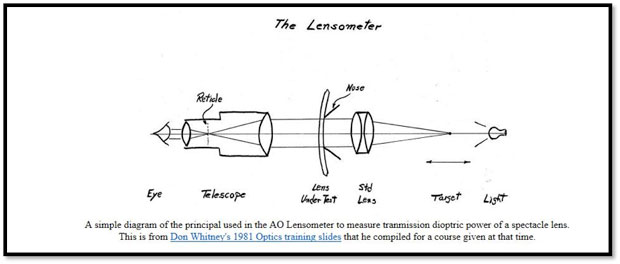
This next description is from an AO 1951 procedure that my father Don Whitney wrote, describing the well-established practice at that time:
"The Lensometer measures "effective power" with parallel light entering one surface of the lens. For this reason, this effective power will give a true picture of what the patient sees for distant vision. The actual Lensometer "effective power" of a prescription for near is seldom known and it does not enter into the prescription. What is known is that a plus lens of a certain value is added on to the front of the distance prescription. In measuring a bifocal addition, therefore, we want to determine the power of this plus lens alone (the segment) and not the power of the combined reading and distance portions.
The question often raised is how this is accomplished by reversing the lens on the Lensometer. This can best be seen by considering a lens with a plano distance portion. When the lens is placed with the convex surface of the lens on the positioning tube of the Lensometer, parallel light is entering one side of the segment. This being the case, the power which is read on the Lensometer wheel will be exactly the effective power of the segment alone. As was pointed out above, this is what we are trying to measure.
To read it in its entirety, one can download it (paper #4) from this page on my website.
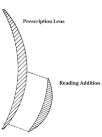
This illustration at left, shows the addition as a separate component. It was used in last month's article discussing the makeup of early glass AO bifocals. As described then, early bifocal lenses were literally cemented on as shown and is why we refer to it as the "add."
The next illustration below was a drawing I made shortly after I joined AO in 1974. I was assigned the task of writing an internal Standard Laboratory Procedure (SLP) for the Lensometer. This was a fortunate exercise for me at that time, because it gave me a reason to delve into the field of ophthalmic optics. It is included here to again show the parallel light for the distance portion, and the RP as a separate lens and the location of parallel light reversed.
Does proper positioning of the lens matter when measuring the lens add?
One might ask, is the turning of the lens to measure the add really all that important? Perhaps I can just ignore this practice and get similar results and make life simpler!
It turns out that errors of add measurement between methods are dependent upon the lens distance power. Lenses that are on flat base curves and are negative in power are much less sensitive to measurement method than are strong plus powers, where significant errors are likely. Let's examine these differences.
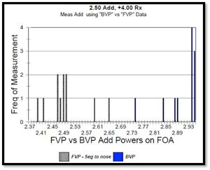
In 2003, I examined data collected in an ISO round robin study, where they were analyzing factors relating focimeter power errors. In that study, known lenses were measured for addition power on multiple units by numerous operators, using both correct and incorrect placement methods. I plotted the errors in this Round Robin study and show two examples here.
This scatter plot represents data points for measurement of the same lens on multiple focimeters. The lens first example shown here was for a +4.00 distance power, +2.50 intended addition power lens. The X axis at the bottom shows the actual dioptric measurement of the addition power, where readings from +2.40 thru +2.95 were obtained when measuring this one lens. The readings that were scattered between +2.75 to +2.95 measured adds were when the test lens was measured incorrectly (not reversed). Errors of between +0.25 and +0.45 D were seen in the incorrectly measured lenses.
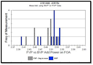
The next example was for a -4.00 diopter lens with an identical +2.50 addition power. It is of a configuration where differences are not significant. The blue measurements indicate measurement data points for when the lens was not reversed.
The ISO committee found the single most important factor influencing errors in power measurement were from improper placement of the lens on the focimeter support.
On a related topic, I led a Vision Council study that resulted in a paper published last year. It studied how lens design and focimeter may further influence the magnitude of power measurement errors—most notably for add. This is available via the Vision Council, and if interested in this topic I encourage you to read it.
I hope this article has been useful to gain a better understanding of how and why traditional bifocals are measured the way they are.