By Barry Santini
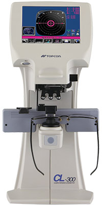
The auto lensmeter can toggle between different lens material abbe values and which wavelength standard you prefer in determining dioptric value. Today, it sits alongside the manual model in any lab.
The year 2020 is an auspicious year—not only because of the importance the eyecare industry places on that particular number—but also because it marks the 100th anniversary of the introduction of the first practical commercial lensmeter for the measurement of effective ophthalmic lens power. The design familiar in form to us today was introduced by American Optical as the Lensometer, which is an AO trademark, after more than 10 years of development. (In this article, the term lensmeter will be used when referring to the generic device, whereas Lensometer refers only to the AO instruments.)
Before we begin exploring the history and development of the lensmeter, let’s first take a closer look at this most essential of optical instruments. Even if you’re familiar with lensmeters and how they work, there are a few things to always keep in mind when you sit down behind what many opticians call their “best friend.” Here are some of the basic protocols that I follow on a daily basis.
THE DAILY GRIND
When you first sit down with your lensmeter for the day, you should:
- Focus the eyepiece by racking it fully outward, then slowly turn it back in until the prism reticle first appears sharp. This procedure corrects for the influence of operator eye error and accommodation. Note: Some operators advise placing a white piece of paper under the lens clamp to further help in determining reticle focus.
- Use a soft lens brush with bellows to gently brush and blow off any dust on the exposed eyepiece lens. If the eye-lens is smudged, use a slightly moistened microfiber cloth to remove the smudge.
- If possible, remove the lens stop and brush or blow off any dust in a similar manner.
- Turn axis wheel to 180 degrees, and turn the reticle axis dial so it lines up with the 180 axis mire.
- Ensure the target mire is centered in the middle of the reticle.
- Focus the mire with no lens clamped in place. Note if power drum reads other than “0.00” (Plano). Any difference should be noted and carried to correct the powers found.
THE LENSMETER BLIND DATE
ECPs who work at multiple offices often have to use a lensmeter that they haven’t met before—aka a “blind date.” Anytime you approach a lensmeter you haven’t used before, the six points mentioned above should be employed, along with the following:
- Verify that the axis wheel rotates without the mire rotating in a circle around the center of the reticle. Correction requires a service technician.
- Verify the target mire is precisely centered in reticle. Correction may require either adjustment of the field lens or realignment of the telescope. Either procedure requires a service technician. Note: If your lensmeter is equipped with a rotary prism compensator, this may be not zeroed out or aligned properly. This can be quickly adjusted by the operator.
- Verify the marking device—With the target mire verified as properly centered, grab a sphero-cylindrical lens of a reasonable power—say a -2.00DS -2.00DC. With the axis set to 180 and the reticle aligned to the same, carefully center the lens and read it in minus cylinder fashion. Check through focus to ensure both meridians of the mire are precisely centered in the middle of the reticle. Now mark the lens. Carefully remove the lens and turn it 180 degrees. Center again and remark. Ideally, the second set of marking dots should be superimposed over the first set. Any error seen should be measured. Regarding the center dot, the tolerance in marking alignment is half of the ink dot diameter. Note that a 1 mm difference in center dot superimposition indicates half that value is the error. Example: A 1 mm displacement of the center dot indicates a 0.5 mm marker misalignment error. This applies to both horizontal or vertical meridians. Also note the axis superimposition of all three dots. Any displacement here reveals the marker is not precisely on axis, and the difference found is also twice the error. A skilled operator may be able to adjust the marker, but time and patience is required. A service technician may be required.
- If the power drum is found to not zero out at Plano using the procedure outlined above, a quick shortcut for compensating for this error is to set the power drum to Plano and refocus the eyepiece using the target mire instead of the reticle. This may result in the reticle being slightly out of focus, which some technicians say might stimulate unwanted accommodation. This suggestion is a quick work around when the lensmeter is a “blind date.”
- Take multiple readings. Even with a known and well calibrated instrument, it is advisable to take at least three readings and average them for the best result. Research at American Optical suggests that skilled operators can improve accuracy by averaging at least 10 readings.
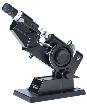
The manual lensmeter of today has rightly earned the trust and respect of optical
professionals across the globe. Incorrect
or improper use can make or break an ECP’s reputation.
THE PROGRESSIVE LENS BLIND DATE
When verifying an uncut progressive lens, this is the procedure I’ve developed to ensure compliance with ANSI standards and maintain high quality. Note that the progressive lens must have its engraved markings in place before commencing this procedure:
- Wave Inspection—I will hold the concave side of the lens approximately 4 to 6 inches from my eye and move it back and forth across my gaze while looking at a page of text approximately 8 to 12 inches away. I am scanning for any gross surface waves or defect in the area around the PRP Distance Verification Circle. I have found letters and words help quickly reveal unwanted surface issues. I start this evaluation with the LEFT lens.
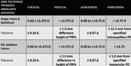
- Prism and Imbalance Verification—While still holding the left lens, I position it in my lensmeter, against the lens stop, while attempting to center the (already marked) prism reference point (PRP) in the center of the aperture. After applying the lens clamp, I trial mark the lens, noting if the center dot of the marker is exactly coincident with the PRP dot. I recenter the lens and repeat until the two dots exactly coincide. I note if any prism in any direction is present and if any horizontal prism was indicated on the work order. I hold these values in my (very) short-term memory.
- Review Right Lens for Points 1 and 2—I now repeat the same wave and prism inspection prism for the Right lens. Findings are noted on a temporary piece of paper.
- Right Lens Distance Rx Verification—With the Right lens still in the lensmeter, I move the lens down until I have the distance verification zone centered around the aperture. Using the Rx or compensated Rx values provided—if any—I now set the axis wheel as needed. The appropriate values are then compared to my readings—although I am less concerned with power tolerances at this juncture. I then dot the lens with the marker, remove the lens from the instrument, and note the axis alignment of the marker dots against the horizon indicated by the engravings. Differences are noted, but no tolerance evaluation, as yet, is applied. The polarization axis is checked at this time, using an axis checker I have taped up in my field of view.
- Left Lens Distance Rx Verification—a repeat of number 4 with the left lens.
- Tolerancing of Lens Power and axis using an Auto Lensmeter—Now I move onto my auto lensmeter to read Sphere, Cyl and Axis. Here is where I will note—but not fail—any lens outside ANSI specs. My auto lensmeter is toggled to a precision of 0.01D and an “averaged” abbe value of 45. I will often have to “move the lens around” to see if I find a value within tolerance, as this precision setting is quite sensitive. If any parameter or parameters are suspect, I will reinspect using the standard manual model and make a final judgement.
From here on, decisions to pass or fail any lens at this stage requires more information than the work order alone. (See “Judgement Day” below).
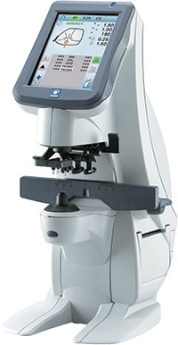
Auto lensmeters have the advantage
of being able to toggle dioptric readings
to 0.25D, 0.12D or 0.01D. But the promise of increased accuracy can be influenced
by the instrument’s unique “fingerprint.”
SEEING BEYOND THE LENSMETER
It’s common for the majority of eyecare professionals to refer to prescriptions and glasses in terms of correct or incorrect and right or wrong. This, I firmly believe, sells the nuance of the entire eyewear visual experience quite short. The determination of what makes a pair of prescription spectacles satisfactory—aka 20/Happy—is the culmination of evaluating quite a lot of moving parts. Because of all these moving parts and to ensure quality, we’ve established tolerances for individual lens parameters and completed spectacles. Remember: Tolerances aren’t always about what can or could be done. The better tolerances are informed by what should be done. And judgments regarding where and when to strictly apply the standard tolerances should always remain similarly informed.
ACCURACY AND THE LENSMETER
I am sure every operator thinks that the readings they obtain are accurate. But I also think it is instructive to understand exactly what degree of precision and accuracy is possible with any type of lensmeter. Luckily, we have the work of a noted lens AO engineer, Don Whitney (father of Dick Whitney, the current curator of the Optical Heritage Museum in Southbridge, Mass., and present chair of the ANSI Z80.1 committee) to draw on to help answer these questions.
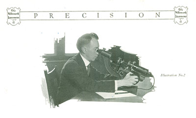
A trained operator using a well calibrated instrument is capable
of obtaining lens powers featuring an accuracy of 0.03 diopters
In the late 1970s, the optical industry was under assault. With the rise of eyeglasses as true fashion, along with a growing consumerism movement, there was a feeling in some government circles that the ECPs were unfairly restricting the choices of eyeglass buyers. This first manifested itself in the FTC’s Spectacle Release law, which tried to address the practice of offices holding the consumer’s eyeglass prescription hostage. At the same time this law was passed, there was also movement to allow the sale of over-the-counter (OTC) reading glasses without a doctor’s prescription. Concurrently, the FTC was exploring whether there were tangible risks to the public in allowing wearers to have their present glasses duplicated via neutralization, i.e., without a written prescription. Don Whitney exchanged correspondence with the FTC regarding his team’s work into the area of operator consistency, precision and accuracy using a manually-focused lensmeter to record lens readings. AO had recently presented the Model 12620 Lensometer—a modification of the just introduced Model 12603—but with an electronic readout of lens power that could be set to the unheard of precision of 0.01 diopters! The use of Model 12620 informed AO’s conclusions on operator accuracy and precision.
Don Whitney showed the FTC that two factors were at play in Lensometry readings: 1. The accuracy of the manufactured instrument, and 2. The operator’s ability to consistently obtain similar readings of an individual lens.
What Whitney found was:
- Manufacturer accuracy in AO Lensometers—These were calibrated with lenses traceable to the National Bureau of Standards—were traceable to 0.03D at 95 percent certainty.
- The repeatability of operator readings was found to lie between 0.05D and 0.03D, depending on whether the operator was of “average” skill or a “trained” operator, respectively.
- Whitney further noted a trained operator could refine their power reading accuracy to as low as 0.01D by taking 10 separate readings and averaging them for the result.
–BS
JUDGEMENT DAY
I’ve written before in my “Don’t Act like a Lab” story that the lab is the only of the three optical entities—prescriber, fulfiller and fabricator (lab)—that can actually judge whether an uncut lens or pair of spectacles is really right or wrong. In essence, what a lab is doing is making a “pass or fail” judgement against a simple work ticket. But as a dispenser/fulfiller, you have far more information available to you with which to more comprehensively determine if a lens or pair of glasses is satisfactory for a particular patient.
A skilled dispenser would know (try saying it with a “Back to the Future” cadence):
1. Where the Rx has been (Previous Rx)
2. Where the Rx is now (Present Rx)
3. Where the Rx is going (New Rx)
Consequently, the level of sophisticated information a dispenser has available to them is several tiers above that of a lab. I believe dispensers have a mandate and responsibility to use that information in every lens and eyeglass judgement they make.
THE LENSMETER OF THE FUTURE
I thought it would be fun to put together a short wish list of features I’d like to see in a next-generation lensmeter:
- Miniature LED lights on the marker pins to facilitate centering a free form lens’ prism reference point (PRP) and help in making prismatic power and imbalance evaluations.
- A white or lighter background around the lens stop in order to see the marking dots and or engravings which indicate the position of the lens’ functional horizon line.
- The next two features are unashamedly stolen from my experience with AO’s 12620 digital electronic readout Lensometer:
- The ability to electronically zero out power to Plano, aka “0.00”
- The ability to store individual meridian readings and have the difference—the power of the cylinder—automatically displayed in either plus and minus cylinder form.
- Plenty of room on the frame table for evaluating wrap and sports frames.
What other features would you like to see?
CELEBRATING THE ORIGINS OF LENSOMETRY
The introduction of the Lensometer effectively marked the beginning of a 50 year “golden era” in American optics, when AO and its chief rival, Bausch & Lomb, elevated the United States to the position of world leadership in ophthalmic optics, instruments and eyeglass-related technologies. There’s no better time than this centenary to celebrate the lensmeter’s creation, development and history, and to discover how it became so completely woven into the daily life of an optical office and lab that its users—to a person—agree the only way they’d give it up is for someone to “pry it from their cold dead hands.”
Just what kind of instrument could engender this type of loyalty? Certainly only one that could create a deep feeling of intimacy with its operator. After all—you are in the “kissing zone” when you’re up close with a lensmeter’s eyepiece. But today, despite having sophisticated alternates for measuring lens power—the auto lensmeter and the lens mapper, which promise either more precise readings or a portrait of the lens surface in question—the standard lensmeter reigns supreme because it delivers what an ECP truly values: A visual and qualitative picture of exactly what’s going on in the lens under review. Because of this, the manual lensmeter is the most important instrument used by optician, prescriber or lab—and all agree it deserves the highest levels of respect. I can think of no other single tool that can make—or through misuse—effectively break an eyecare professional’s reputation. For an instrument capable of such power, we should visit the optical era from which it was born.
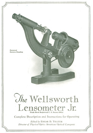
Early lensometers carried the Wellsworth name, as this was an instrument-making
company previously purchased by American Optical
THE AGE OF THE LENS EXPLORER
The 19th Century should rightfully be thought of as the explorer’s age for human vision. From Wollaston’s exploration, starting in 1804, into making lenses with wide views of view, to Young and Airy’s pursuit to solve the riddle of astigmatism, much empirical experimentation and thought was being put into the birth of the science we know as optics. The 19th century was also home to most of the familiar names of optics: Gauss, von Helmholtz, Listing, Monoyer, Nagel, Gullstrand, Badal, Abbe, Javal, Snellen, Donders, Percival, Ostwalt, Tscherning and Prentice. All of these visionaries worked tirelessly to elevate the understanding of human vision from its dark ages and created most of the scientific and mathematical foundations that comprise the discipline of ophthalmic optics.
DEFINING LENS POWER
In the early 1800s, a world based on a universal measuring standard was still a dream. As the use of lenses to correct vision progressed, one of the challenges was a lack of uniformity in defining and labeling lens power. The reference then used for lens focal length was based on the inch of the old English system, but the inch was not yet precisely defined and varied in regions around the world. Fortunately, a more uniform system of measurement based on natural objects and decimals—the metric system—was being proposed in France. But it would take until 1866, when the ophthalmologist Nagel suggested using this new metric system for measuring lens focal length in a more consistent manner. Then in 1872, Monoyer of France coined the term dioptre to create a relationship between lens power and focal length based on the metre. Together, these two innovations—the use of the metre and the dioptre—were the first steps in separating the unique requirements of ophthalmic lenses from those used in general, technical and photographic optics. Still, determining the power of an eyeglass lens remained an imprecise process. The typical optician of the day would assess an unknown lens by moving it across a distant object. Viewing the distant object’s resultant motion, the optician would then try moving various lenses of “known” opposite power across the lens in question, until the target’s motion was canceled, or “neutralized.” This became the skill known as hand neutralization, and even today, we continue to refer to verifying power as neutralization.
KNOWLEDGE IS POWER
In the early years of the 20th century, ophthalmic lenses began transitioning from an empirical science to one more firmly grounded in technically sound mathematical and optical principles. To that end, it became clear that work needed to be done to ensure that both vision testing and prescription eyeglass fulfillment precisely met the needs of the wearer. In the world of technical optics—telescopes, binoculars, microscopes and the like—it was routine to measure focal lengths using the concepts of principle points and planes as the reference points. However, in the world of ophthalmic lenses, the location of a lens’ principle points varies with lens curve, form and thickness. Therefore, a more suitable way of defining ophthalmic lens power—one which encompassed the requirements of both trial and eyeglass frame—was created called vertex power. This defined lens focal length as measured from the peak curvature of the rear lens surface—the vertex—regardless of the lens’ form. In this way, the shape and thickness of a lens placed in front of the eye were no longer factors influencing its dioptric power. All the lens forms in use at the time—plano convex/concave, double convex/concave, and the manifold forms of meniscus lenses—periscopic, coquille, Wollaston, Ostwald, etc., could all enjoy a uniform way of defining their effective power in front of the eye. Vertex power is also referred to as back vertex power or effective power. Now all that was left was to find a convenient way for manufacturer, prescriber and lab to measure vertex power.
THE CHALLENGE OF MEASURING VERTEX POWER
The three main challenges facing the creation of a practical vertex power lensmeter were:
- Translating the measurement of focal length from geometric to linear—Clearly, measuring the actual back focal length of a 0.25D lens, which is 4 meters, would dictate an instrument of impractical proportions. What was needed was a way to compress the size of the instrument and make the focal length readings readable using a linear rather than geometric scale.
- Make the target mire comfortable to view, uniform in size and stable in luminance—determining the focal length, i.e., power of an unknown lens requires varying a target’s distance to discover where its focus lies. Along with the lens’ power, these two factors would clearly impact the observed size and brightness of the target image. Therefore, a way of ensuring the target image would remain a comfortable size and uniform in scale and brightness became important.
- A way of inspecting the target image formed by an unknown spectacle lens that would not be influenced by either operator eye error or variations in operator accommodation.
How all three of these challenges were met was revealed in Edgar L. Tillyer’s 1920 paper for the first commercially successful AO Lensometer. By employing a standard/field lens of specific power—traceable to a known standard—positioned in compliance with a principle first outlined by the ophthalmologist Dr. Badal in 1877, and along with a telescope for enlargement and inspection of the target’s image, Tillyer easily met all three of these challenges. This new Lensometer was the culmination of a decade’s efforts. It featured a compact and linear dioptric power scale, uniform target size and luminance, and reduced the impact of operator eye error and accommodation on the accuracy of the ultimate power readings. The instrument presented a consistent 2.5 mm linear distance between full diopter steps and measured a lens using a 6 mm aperture—a value chosen because it approximates the eye’s fully expanded pupil. The instrument’s power range of plus/minus 20 diopters would encompass 99.99 percent of all prescriptions countered.
THE STAGE IS SET FOR SUCCESS
For a number of years, the new Lensometer gained wide acceptance for its ability to quickly determine lens power, axis and prism, and when equipped with a marker, to precisely mark lens centers. Competing manufacturers such as B&L developed their own model, which they trademarked Vertometer. In 1938, American Optical introduced the model 620 Lensometer, which included a frame table, or stage, upon which completed eyewear could be neutralized and verified. Analyzing eyewear for vertical prism imbalance and astigmatic axis became a breeze. And this wonderful instrument has remained more or less unchanged in form and function—right through until today.
ENTER THE AUTO
In 1956, American Optical became the first company to create an electronic automatic focusing Lensometer featuring a precision digital readout. The team that designed this instrument included Donald Whitney, who would later use this experience in the development of the Model 12620 digital reading manual Lensometer released in 1978. Over the years, automatic lensmeters have also become important tools to the optical office and lab.
Here’s where auto lensmeters excel:
1. Power reading precision to 0.01 diopter.
2. Ability to enter the abbe value of the lens material in order to further refine the power reading.
3. Ability to toggle between the two competing world standards of 546 nm and 587 nm in selecting the preferred reference wavelength value for defining diopter power.
But electronic circuits, as audiophiles have long known, can influence the final result obtained because they have their own unique imprint that standard makers refer to as an instrument’s fingerprint. So despite promising an accuracy of 0.01D, most automatic models, because of their unique fingerprint, are actually no more accurate at 0.03D than a well calibrated manual instrument used by a skilled operator.
THE TRIAL OF TRIAL LENSES
All these efforts regarding effective lens power and accuracy would be for naught if there wasn’t a clear correspondence between the lens power used to prescribe and that used to fill an Rx. For successfully meeting this challenge, we have to thank Charles Prentice—the first to design a trial set for refraction whose lenses possessed a form and labeling that would permit them to be stacked together and their values summed for an accurate final prescription. In 1900, American Optical introduced the first trial set based on Prentice’s design, and these lenses represented an early attempt toward the fuller concept of vertex power, formally introduced later by Von Rohr of Zeiss.
ONE INDEX TO GUIDE THEM
It is interesting to note that lenses designated by vertex power are also free of influence from the lens material’s index of refraction. This is important because in the early years of the 20th century, crown glass was transitioning from “old” ophthalmic crown having an index of 1.53, which was actually 1.528 index rounded to 1.53, to modern ophthalmic crown having an index of 1.523.
–BS
THE FOREST FOR THE TREES
Ours is a visual science and a visual industry. I think this alone explains why the lensmeter remains the benchmark instrument of today’s eyecare professional, 100 years after its introduction. But while ECPs continue to proudly demonstrate their skills of precision and accuracy behind the eyepiece, don’t let that eyepiece obscure seeing what is truly important for the eyeglass wearer: It’s never about the glasses being right or wrong. It’s always been about solving problems, making adjustments, creating satisfaction and forming a trustful relationship with the wearer. If a patient takes their Rx elsewhere for glasses, and returns with problems, try to avoid politicizing this fragmentation by harboring sour grapes about the loss of an eyeglass sale. Instead, welcome the opportunity to verify the Rx. If it matches what’s written, recognize that this is actually the best scenario for a brick-and-mortar optical to be in. Now the story of full eyeglass satisfaction can pivot to discuss all the ingredients that go into the making of truly great eyewear. Seen from this perspective, the lensmeter becomes as important to your patient’s vision as it is to your bottom line. So please give your lensmeter all the respect it has so rightfully earned—and use it wisely. ■
The author thanks Dick Whitney and Brent McCardle of Carl Zeiss for their assistance with this article. Special mention must be made to Dick Whitney in his role as head of the Optical Heritage Museum and with his website dickwhitney.net. His willingness to share many historic papers on the history of vertex power, lensmeter accuracy and other practical information regarding ophthalmic lenses made this story possible.
A recognition event for the introduction of the AO Lensometer sponsored by the ASME and the Optical Heritage Museum is planned for 2021.
Contributing editor Barry Santini is a New York State licensed optician and contact lens fitter with Long Island Opticians in Seaford, N.Y.


