

By Kai Rands
Opticians inspect and verify ophthalmic lenses as a part of daily practice. We are responsible for ensuring the lenses are free of defects and that the lens specifications are accurate and fall within ANSI tolerances. By their own definition, “ANSI Z80-1 – 2015 applies to all prescription dress ophthalmic spectacle lenses in edged or assembled form. It is a guideline for entities that fabricate, assemble or process dress eyewear or lens components. Relevant optical and physical specifications and tolerances of this standard also apply to uncut lenses.” The ANSI standards go into depth about the expectations for lens specifications. Honing our verification expertise entails applying measurement methods that identify if lens parameters are within the ANSI tolerances.
STANDARDS FOR PRESCRIPTION OPHTHALMIC LENSES
Since 1972, committees have written eight revised versions of the Z80.1 standards. The most recent version is ANSI Z80.1-2020. These standards are specific to dress (non-safety) mounted or assembled prescription eyewear. The American National Standards Institute serves to guide U.S. opticians. Internationally, the International Organization for Standardization has developed similar recommendations for ophthalmic lenses (ISO 13666:2019).
The standards are guidelines, not regulations. Although opticians are not legally bound to follow the standards, doing so is professionally responsible and serves the best interest of patients.
VERIFICATION TOLERANCES FOR REFRACTIVE POWERS
Accurately verifying refractive power takes on new importance when we realize that inaccurate verification can be detrimental for patients. When inaccurate refractive powers are missed during verification, patients may experience induced anisometropia. Induced anisometropia (unequal refractive power) can potentially affect binocular function. In a 2023 article in the International Journal of Ophthalmology, a team of researchers in China led by Xu-Bo Yang found that as induced anisometropia increased, several types of binocular function decreased.
Sphere meridian power and cylinder power, and axis are verified against the written prescription and never against the lab order. Always adjust the eyepiece on manual lensmeters to your eye before neutralizing a lens. In the verification process, use minus cylinder form. If the Rx has been compensated based on position-of-wear measurements, the compensated values are used. This is because the compensated power more accurately reproduces the prescribed power. A compensated freeform lens design optimizes the lens surface to adjust for visual impact of frame fit, for example vertex distance and tilt, to better reproduce the intended visual experience as prescribed for the patient.
Sphere and cylinder power tolerance for low refractive powers are based on set numerical values. For example, a single vision lens with a sphere meridian power of -6.50 D to +6.50 D has a sphere power tolerance range of 0.13 D higher or lower than the prescribed sphere power.
Higher refractive power tolerance ranges are based on percentages rather than set numerical powers. This is true for single vision lenses (including lenses for distance vision or any other working distance), multifocal lenses, as well as power variation lenses with more than one reference point and for both sphere and cylinder power. In the full ANSI Z80.1 document, Section 5.1.1.1 Table 1, p. 12 lists the tolerance ranges for any type of lens with a single reference point as well as segmented multifocal lenses. Section 5.1.1.2 Table 2 (p. 12) lists the tolerance ranges for any type of lens with more than one reference point.
CALCULATING SPHERE MERIDIAN POWER TOLERANCE FOR HIGH REFRACTIVE POWERS
The sphere meridian power tolerance range for lenses with a single reference point and segmented multifocal lenses whose sphere power is stronger than +/-6.50 D is +/-2 percent. For example, let’s say that a patient has the following Rx:
OD -11.50 +4.00 x 080
OS -14.50 + 5.00 x 090
First transpose the Rx from plus cylinder to minus cylinder. To transpose, add the cylinder to the sphere power—this value is the sphere power. Then change the sign of the cylinder to (-) and change the axis by 90 degrees (+/-). We get the following when we transpose the plus cylinder Rx above to minus cylinder:
OD –7.50 -4.00 x 170
OS -9.50 -5.00 x 180
For the sphere powers, the cylinder powers and the axes, the auto-lensmeter reads:
OD -7.68 -4.10 x 172
OS -9.68 -5.12 x 003
The OD sphere power is off by 7.68 - 7.50 = 0.18 D. To find out whether 0.18 D is outside of the tolerance range, we find 2 percent of the absolute value of the prescribed/compensated sphere power, 7.50 D:
7.50 * 0.02 = 0.15 D
The sphere power tolerance is 0.15 D but the power for the right lens is actually off by 0.18 D. Another way to look at this is that the sphere power falls within the tolerance range if the read power is between -7.50 - 0.15 = -7.65 D and -7.50 + 0.15 = -7.35 D. The power read in the auto-lensmeter is -7.68 D, which is not within this tolerance range. The sphere power for the right lens does not “pass” inspection.
The OS sphere power is off by 9.68 - 9.50 = 0.18 D. The OS sphere power reading is off by the same amount as the OD sphere power. However, since 9.50 D is stronger than 7.50 D, 2 percent of the prescribed/compensated power will be higher for the OS lens than for the OD lens. To find the OS sphere power tolerance range, we can calculate:
9.50 * 0.02 = 0.19 D
For the left lens, the sphere power is allowed to be off by 0.19 D and is only off by 0.18 D. We can also calculate the tolerance range by subtracting and adding 0.19 D to the prescribed/ compensated sphere power. The read sphere power should be between -9.50 - 0.19 = -9.69 D and -9.50 + 0.19 = -9.31 D. The read sphere power, -9.68 D, is (barely) within this tolerance range.
ACCURACY VERSUS PRECISION WITH MANUAL AND AUTO-LENSMETERS
The sphere power reading for the left lens was on the very border of the tolerance range—off by only 0.01 D. The ANSI Z80.1 standards discuss this issue in Annex F. Just because auto-lensmeters often produce readings to the hundredths of a diopter does not mean they are more accurate than standard manual lensmeters. In borderline cases (whether using a manual or auto-lensmeter) it is helpful to take repeated measurements on the same device and on different devices. Auto-lensmeters typically also have the option to round to different increments, such as 0.12 D increments. If this option was used for the left lens, -9.68 D would round to -9.62 D, landing the reading clearly within the tolerance range. However, if the auto-lensmeter was calibrated slightly differently, and the reading was -9.69 D in 0.01 D increments, rounding to 0.12 D increments would yield -9.75 D, which is clearly outside the tolerance range. On a manual lensmeter, which uses an analog system, the optician makes a visual judgment.
EFFECTS OF PRISM
Prism has consequences for binocular vision. People living with various systemic and eye conditions benefit from prescribed prism. For example, the autoimmune condition Graves Eye Disease causes extraocular muscle cells to become inflamed. The inferior and medial rectus muscles are most commonly affected leading to hypo- and esotropia. Eyecare professionals can use prism to affect the interaction between light deviation, image displacement and neural processing to influence binocular vision. When hypo and esotropia occur together, oblique prism may prevent diplopia for some patients.
Prism can also be unwanted, induced through centration errors or vertical prism imbalance of 1 diopter prism difference between the right and left eyes as they drop in the lens to read in a lined multifocal lens. Vertical prism imbalance is caused by anisometropia (unequal refractive power) between the right and left lenses. It will be covered in a future article.
Unwanted prism can lead to diplopia or visual distortion such as perceiving walls as slanted. Physical discomfort such as asthenopia, headaches and dizziness can also occur. In this article, we will address induced prism tolerances. Correct verification of prism is important so that patients gain the benefits of prescribed prism when it is prescribed, and detrimental effects of unwanted prism are avoided.
LOW PRISM
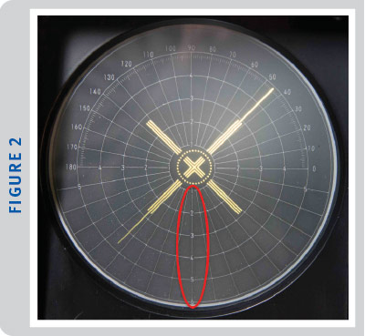
Opticians can use the concentric circles on the reticle of a manual lensmeter to measure low amounts of prescribed prism (0^ to 5^). (See Figure 2.) The major reference point (MRP) is the point on the lens that produces the amount of prismatic effect specified by the prescription. For single vision and segmented multifocal lenses with no prescribed prism, the MRP is the same as the optical center (OC), the location on the lens through which light rays pass without deviation. For lenses with prescribed prism, the MRP will be different from the location of the OC. The OC will be decentered from the visual axis so that the patient will experience the desired prismatic effect when viewing through the MRP.
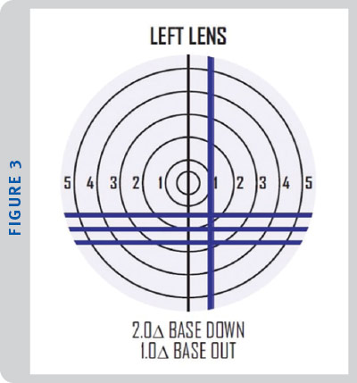
Begin with the lens with the strongest refractive power along the 90 degree vertical meridian. (Use the oblique meridian formula if this is not obvious from the Rxs). For non-aspheric single vision and segmented multifocal lenses, center the crosshairs at the location specified by the prism in the Rx. For vertical prism, the crosshairs will be above the center of the reticle for base up prism or below the center of the reticle for base down prism. In other words, the concentric circle hash marks serve as a number line. The same concentric circle hash marks serve as a number line for horizontal prism. For horizontal prism, you must take into consideration the direction for in (nasal) or out (temporal) on the lens. For example, for the right lens with base out prism, slide the frame horizontally so that the cross hairs are to the left of the center of the reticle, since left is toward the temporal edge when looking at the front surface of the lens. Positioning the MRP for lenses with prescribed oblique prism combines vertical and horizontal coordinates known as rectangular coordinates (base up, down, in or out). In Figure 3, the Rx for the left lens is OS -2.00 -1.00 x 180 2^BD 1^BO.
Since the axis meridian is 180, the sphere mires will be horizontal, and the cylinder lines will be vertical. We can use the mires like the axes on a Cartesian plane. We position the horizontal mire so that it crosses directly through the hash mark labeled 2 below the reticle center. We position the center vertical mire so that it crosses directly through the hash mark labeled 1 to the right (temporal) of the reticle center. When the axis meridian is not 090 or 180, we can still imagine a Cartesian plane overlying the reticle. Consider the Rx OD -2.00 -1.00 x 060 3^BU 2^BI, pictured in Figure 4.
Line A represents the sphere mires at 060 degrees, and line B represents the cylinder mires at 150 degrees. To locate 3^BU, we overlay imaginary horizontal line C along the third ring above the center of the reticle. To locate 2^BI, we overlay imaginary vertical line D along the second ring to the right (nasal) of the center of the reticle. Note that the crosshairs fall between the third and fourth ring. Oblique prism can also be written in polar coordinates as illustrated by the dotted line. The length of the dotted line represents the amount of oblique prism. The oblique prism angle (direction of the base) is the angle the dotted line forms with the horizontal axis (with the vertex at the center of the reticle). In this case, the amount of prism is 3.6^, and the angle of the prism base is 056 degrees. The Rx OD 3^BU 2^BI is equivalent to OD 3.6^ @ 056 BU&I (in 180-degree notation) or simply OD 3.6^ @ 056 (in 360-degree notation). Polar form is typically used by labs and occasionally by prescribers.

High Prism
What if the prescribed prism is higher than 5^, such as for the OS lens example given in the section about verifying high sphere powers? The prism compensating device (PCD) extends the verification range for prism. The PCD requires using polar coordinate form. If the prescribed prism is not written in polar coordinates form, you can use the resultant prism trigonomic formula to convert rectangular coordinates to polar coordinates form. The PCD consists of two dials. Turning the larger dial sets the angle of the base-axis line. This is equivalent to using the protractor ring for prism amounts 5^ or less. The second dial moves the crosshairs along the base-apex line into view on the reticle. When looking at the lensmeter from above, you can see a small stainless steel knob. Setting the base-apex line to the proper angle entails using the small knob as a lever to rotate the larger dial. When positioned to look through the lensmeter eyepiece, the angle measures are marked around the larger dial from 0 degrees on the right to 180 degrees on the left as if the dial markings corresponded to the angle markings on the reticle. You can read the base-apex line angle from a tick mark aligned with the small knob. For verification, align the tick mark with the base-apex line angle based on the prescribed prism in polar form. The second dial, which moves the crosshairs into view, is the small knob itself. Once the base-apex line angle is set, rotate the small knob itself until the crosshairs are positioned in the center of the reticle, as if there were no prism. As the crosshairs move toward the reticle center, the second dial turns to indicate the amount of prism “compensated.” For example, for a 6^ lens, turning the dial to 1 will move the crosshairs onto the concentric circle labeled 5 on the reticle because the PCD has compensated for 1 of the 6 prism diopters. When the crosshairs are centered in the reticle, the prism diopter power scale indicates the full amount of prism at the MRP, in this case, 6^.
Let’s consider the previous example with a high refractive power but with added prescribed prism:
OS -14.50 + 5.00 x 090 7^BO 2^BD
To verify the prescribed prism, first we need to convert to 360-degree notation polar form, which is OS 7.3^ @ 344. The problem is that the base-apex line angle range is only 0 to 180 degrees. To account for this issue, the prism diopter power scale has prism diopter increments in one direction marked in white and in the other direction marked in red. If the prism diopter reading is in the red range, you add 180 degrees to the base-apex angle. In this example, the base-apex angle is 344 degrees. Since 344 degrees is not between 0 and 180 degrees, we should set the prism diopter power scale to red 7.3^. Now we want the sum of the angle indicated on the large dial and 180 degrees to equal 344 degrees. Algebraically, we have x + 180 = 344 where x is the angle at which we should set the large dial. Solving the equation results in x = 164 degrees. So, we set the base-apex angle dial to 164 degrees and the prism diopter power scale to red 7.3^. When the crosshairs are centered in the reticle, dotting the lens should indicate the MRP.
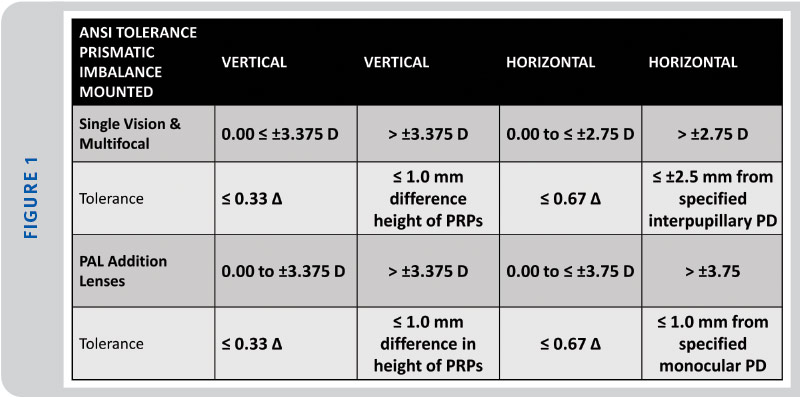
Once the lens is positioned in the lensmeter according to the prescription, the next step is to dot the lens. The locations of the center dots on the lenses should correspond with the PD and height measurements specified. The ANSI standards specify tolerance ranges for the location of the prism reference point (PRP) as well as vertical prismatic imbalance between the lenses.
CONCLUSION
Honing our verification expertise requires that we learn the nuances of the ANSI standards and how to apply them, so that we deliver the best lenses to provide the best visual experiences for the patient.
Kai Rands is a licensed optician who provides optical visual aids to those with low vision.