
Introduction
I have been thinking about topics that might be of interest to the readers of the Opticians Handbook and I began thinking about a number of “old devices/inspection techniques” still used today that would be fun to write about and perhaps give the reader some new information of interest and the lens measure (lens watch or lens clock) came to mind.
In my last article, I gave an overview of the on the topic of the Diopter as it pertains to surface curvature. A simple tool to measure the surface curvature of lenses is the Geneva Lens Measure, it was first patented in the US Feb 24,1891. It is a simple 3-point contact gauge, and the basic principle and design is unchanged since its first introduction.
The Geneva lens measure device shown on the left in the picture below is marked with the 1891 patent date and is on display at the Optical Heritage Museum in Southbridge, Massachusetts. The lens measure or “watch” on the right was one I used at American Optical throughout my career and was made in the 1960s.
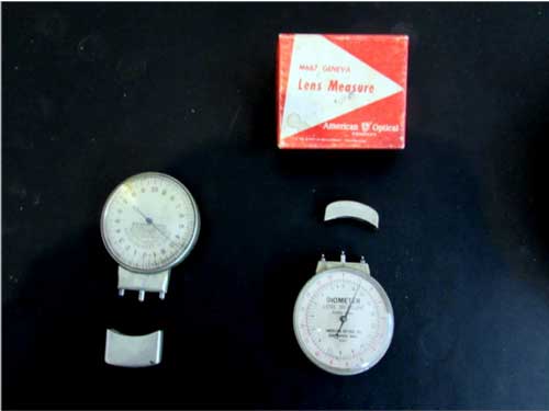
Perhaps not all of you have used such a device, but anyone seeking a quick rough indication of the curvature of a lens will likely have used a similar instrument. Generally the increment of the readout is in 0.25 Diopter steps, and while those skilled with their use might resolve to 0.06 D they are certainly not designed to be accurate to read to 0.01 D. This device is still an important and common tool used for over a century.
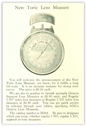
November 1916 AO Advertisement
Lens watches (sometimes called lens clocks) are reliable when measuring uniform (spherical) curves at the points of contact but are not reliable for surfaces that are non-spherical. With the advent of progressive and aspheric lenses, confusion has occurred as to why the readout value from the gauge cannot be considered “accurate” for such surfaces. Lets explore why…
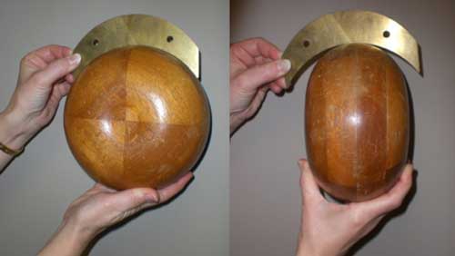
The lens watch is most useful when curve being measured is spherical, that is the surface being measured does not change in surface curvature within the 3 points of contact of the gauge. In this photo below, a 6 Diopter brass gauge is shown to match the curve of the wooden donut model (used at AO for lens design training) on the left. A good match means there will be no openings between the gage and the surface being measured. In the case of the image on the right, the steeper curve does match the gauge but also shows that the surface of the donut on its edge changes and it not spherical. Lets explore how the lens watch behaves when surfaces become aspheric or aberrated.
The schematic diagram below was taken from a 1990’s AO Technical Report on aspheric lenses and their optics. I designed an aspheric lens series at American Optical called Aspherlite, and for its introduction we published a Technical paper, addressing the optics of such lenses.
In the schematic, you will note that two curves are shown being clocked. Both curves meet the 3 points of the measure in such a way as to match the pin depths (lens surface sag) in the same manner. The upper curve marked “sphere” is the type of surface that is anticipated when using the device. The second “asphere” has a central area much steeper than near the edge and therefore is not the same curve but it would measure almost identical if placed on the surface as shown.
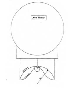
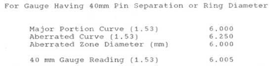
Now let’s look at an example where a localized blip or aberration were present with a significant curve change. If this blip was a 6mm diameter zone with a curvature of 6.25, and the remaining outer surface was a 6.00 Diopter flatter surface, what would the lens watch measure? The answer is surprising. The lens surface would clock to be a 6.01, or basically no different than our 6.00 sphere given the gauge resolution of the device. The center 6.25D curve in the aberrated zone would be undetected if placed as shown.
It is for this reason that surfaces such as progressive and aspheric lens designs may result in errors in absolute curvature readings. This is why lens designers caution against the use of these type of gauges if accurate surface power readings are required.