
By Palmer R. Cook, OD
Every PAL manufacturer offers simple keys to help you use their lens designs to its best advantage. These keys are available, free and should be used routinely with every PAL design. The keys in this case are Centration Charts, and the key words in every dispensary should be no exceptions!


DATA POINTS
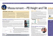
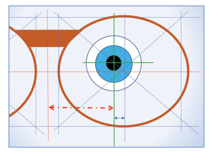
There are four data points for every PAL design (Fig. 1). These include the Distance Reference Point (DRP), the Fitting Cross (FC), the Prism Reference Point (PRP) and the Near Reference Point (NRP). When you specify the height of the benchmark point, (i.e., the FC), you are establishing the locations of the other data points. The monocular PDs define the horizontal distances from the mid-line of the DBL to the points at which the patient’s parallel lines-of-sight intersect the lenses for distance seeing. (Line-of-sight as used here means the ray path conjugate to the patient’s object-of-regard and the fovea centralis.)
In Fig. 1, during straight-ahead distance vision, they would intersect the blue lines above the FC.
THE FRAME
Centration chart use should start with the eyewear design. When approaching a final decision during frame selection, adjust the frame as it will be worn. Then mark an FC height, and do a quick Centration Chart check before the patient falls in love with a frame that will not work. This simple fail-safe takes only a few seconds, and it can save you tons of time and trouble. This can also help an indecisive patient come to a decision, especially if you can safely assure that the frame is well suited for the lens design they need.
CENTRATION CHARTS
Centration charts fulfill two purposes: First they allow you to judge whether the chosen lens design and frame will allow the Rx to work well for the patient’s needs. Second, they give instant verification that the FCs are at the patient’s correct monocular PD locations.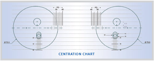
Accurate placement of the frame on the centration chart is critical. Some centration charts require the frame to be positioned twice, once for the right eyewire and again for the left. Others require the frame to be positioned three times, once for the right DRP and NRP, again for the left DRP and NRP, and a third placement for monocular PD verifications. Another common design requires four placements: the basic right and left placements and two additional, one for the right monocular PD, and another for the left. Manufacturers’ representatives should be able to explain and demonstrate the use of the charts for their company’s designs, but standardization is needed. At the very least, every fitting table should have a notebook of laminated charts for the lens designs you are using.
For each placement, the frame must be correctly oriented on the chart. Situations arise in which rotating the frame a few degrees gives the appearance that the patient will have an adequate usable area around the DRPs and NRPs. You must resist the temptation to rotate the frame to achieve an “apparent” fit.
ONE SIZE FITS ALL
Clothing is sometimes promoted with the slogan, “One Size Fits All,” but nothing could be further from the truth with centration charts. The design you are fitting will have a specific centration chart, and that one is the only one that is sure to give you dependable and accurate information. No matter how carefully you measure in placing a Fitting Cross, you must use the correct centration chart if you want your patient to have the best performance that the lenses can offer.
UNDERSTANDING THE FITTING CROSS
The FC is only a reference or marker point. The remaining data points are functional and relate to lens performance. These three points move in lock-step with the FC. The FC should be low enough so the Major Ray Bundle does not overlap the upper edge of either lens. The FC must be located to avoid the same overlap issue for the NRP at the lower edge of the lens. From a practical standpoint, positioning the DRP at least 6 mm below the upper edge of the lens, or positioning the NRP at least 4 mm above the lower edge of the lens is a practical rule of thumb.
The DRP is the point at which the refractive power for distance seeing is measured. The NRP is the point at which the power for near work is measured. The remaining data point, the PRP, is often the optical center of the lens. If prism is found at the PRP it should either be: a. The amount of prism thinning done by the lab to make the lenses thinner and lighter. b. The amount of prescribed prism, or c. Some combination of a. and b.
Single vision and lined lenses have a Major Reference Point (MRP), which is the one point giving the prescribed combination prism effect and power. PALs have no MRP. Their MRP is separated into a DRP and PRP. Keep that in mind when troubleshooting patient difficulties with PALs. Rechecking using the centration chart can be helpful. Also, check the prism at the DRP. If the Rx has oblique cylinder you will find both vertical and lateral prism. The prescribed prism is typically not the prism PAL wearer encounter for either near or distance seeing. If the prism at those points is not “close enough,” adaptation may be difficult or impossible.
Once you have placed the patient’s FC, the locations of the other three data points are fixed, and correctly placing the frame front-side-down on the centration chart will quickly show whether the FC height you have marked will allow the patient full use of his lenses.
THE OPTICIANS’ DILEMMA
Fitting Crosses should be at levels that permit the patient comfortable access to both the DRP and NRP. If the level lines-of-sight pass through the FCs, the patient will need to lower his chin for best vision when viewing distance objects at eye level or below. This is because the intermediate power starts at the FC, so the ray bundle subtending the patient’s macula (i.e., Major Ray Bundle) should fall above the FC for distance viewing. If the level lines-of-sight pass through the DRPs, the patient will need to depress his gaze about 12 degrees (a 6 mm or so drop from the DRPs to the FCs) to reach the beginning of the corridor and perhaps another 30 degrees to reach the NRP. This is a common dilemma when fitting PALs.
Frequently, patients tend to lift their chin when FC heights are measured. As a result, when their head tilt is in a normal position, their level lines-of-sight will usually be above the FCs. This is serendipitous because it helps keep the level lines-of sight above the tops of the corridors.
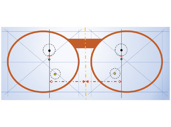
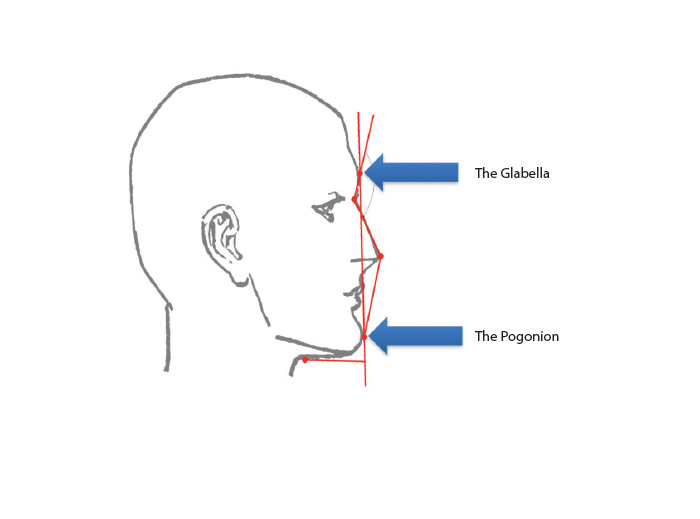
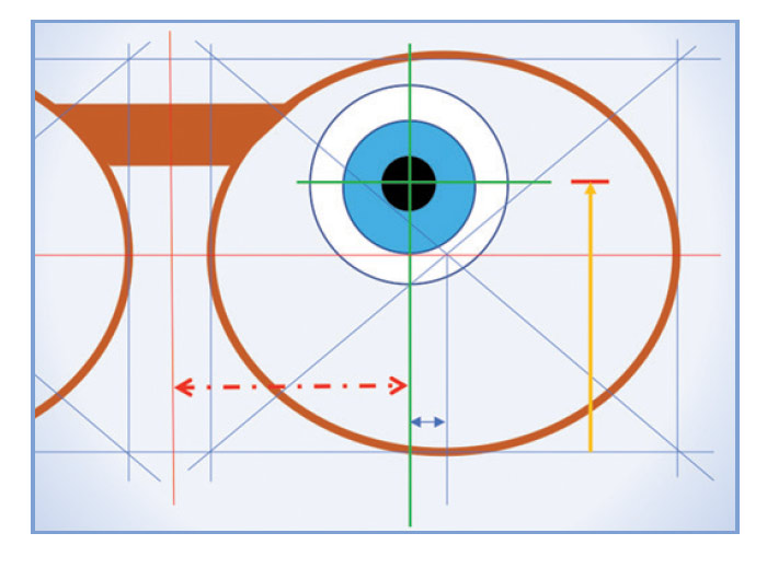
If the height of the pupillary center is marked with the line-of-sight inclined upward, the patient may need to drop his chin in order to see distant objects clearly at his eye level, or when driving. Even placing the FCs at the pupillary centers with the correct head tilt and with the patient’s lines-of-sight level may place them too high for many patients. An alternative method for placing the FC is shown in Fig. 2a and 2b, and 3a and 3b. The short red horizontal line in Fig. 3b and the horizontal blue line both show the height of the patient’s level line-of-sight at the preferred head tilt.
For someone whose critical seeing is primarily at far distances, you might place the DRP at the pupillary center as shown in Fig. 3b. The FC would fall somewhat lower. For primarily near tasks, placing the FC closer to or at the pupillary center might be more appropriate. To determine the best FC location when PALs are ordered: a. Use a system that assures a level line-of-sight. b. Maintain the patient’s preferred head tilt as you measure, and c. Understand the patient’s critical vision requirements.
THE TWO-FOLD CHALLENGE
Centration charts present a two-fold challenge. First the placement of two of the functional PAL points (DRP and NRP) must be such that the patient can fully and conveniently make use of them. The challenges to you and your patient lie in the terms “fully” and “conveniently.” Both the DRP and the NRP are surrounded by lens areas (sweet spots) throughout which the lens’ refractive power is acceptable for distance and near vision respectively.
If the DRPs and NRPs are situated so that their surrounding useful areas are cut off by the frame or lens edges, the patient will not be able to make full use of the lens design. Another challenge is to place the DRPs and NRPs so that their use is convenient. If inconveniently placed, the patient will be required to make excessive head movements for reading, walking or for other vision-based tasks.
Ideally, when you place the chosen frame on the centration chart, the DRPs both will be at least 6 mm or so below the top of the usable portion of the lens. The NRPs both will be far enough (usually about 4 mm or more) above the bottom of the usable portion of the lens for comfort in reading. Patients viewing a 12 cm wide column of print at a 40 cm distance should be able to swing their lines-of-sight about 17 degrees without any head movement. This means the lens design has a near “sweet spot” at least 9 to 10 mm wide.
DISTANCE VISION
If the patient’s preferred frame does not pass the centration chart, decisions are needed. If the DRP is too high, you may be able to drop the FC a bit. If the lens powers are low and/or if your patient’s pupils are small (increasing the depth of field), your patient may be able to see clearly and comfortably a bit further below the DRP. A limiting factor is that the corridor usually begins at the FC so the patient’s vision will decrease in quality as the chin is raised during distance vision.
If you decide to lower the FC to accommodate distance vision, you must be careful that the NRP is not positioned too close to the lower limit of the usable lens area. A shorter corridor could allow the FC to be dropped several millimeters.
NEAR VISION AND MINIMUM FITTING HEIGHT
If the frame limits the lens area for near vision, the problem may be a too-long corridor, or the nasal upsweep may be problematic due to the distance decentration. If too much lens area below the NRP is removed, patients will inevitably be frustrated, but how much is too much? For many years, manufacturers used a measurement they termed the “Minimum Fitting Height” in their marketing. The term often referred to the distance from the FC to the NRP.
Opticians quickly discovered that if they fitted at the advertised minimum fitting height, they were removing at least the lower half of the usable near vision area of the lens. Dispensary managers and ECPs were appalled at the near vision complaints related to fitting at the minimum fitting heights. Some ECPs established a guideline of adding several millimeters to what was advertised and thereby substantially reduced patient complaints.
VARIABLE CORRIDORS
Recently, “variable fitting heights” have been offered. This means your lab will provide the longest workable corridor. This should assure that there will be sufficient near vision area in every patient’s PAL lens. For every problem there is a solution, and for every solution there is at least one problem. One problem with variable corridors is that patients accustomed to wearing frames with a short B measurement may not adapt easily to new lenses in a frame with a longer B measurement, unless the corridor length is kept to the short corridor to which they are accustomed.
Complaints have arisen regarding variable corridors. Patients accustomed to shorter corridors and fitted with a frame with a deeper B measurement may find it awkward to repeatedly adjust their head position and/or the position of repetitive near tasks. One experienced optician with this problem commented, “I use my DRP for the lensmeter and my NRP for viewing the order. The long corridor in my new glasses is needlessly complicating job verification. This is an unappreciated added layer of adaptation that could have been avoided.” Ask your lab to let you know which of your preferred PAL designs are still available in the corridor length you specify, and which will automatically lower the NRP to the lowest possible point.
THE GOTTA-HAVE FRAME
Every ECP has had the uncomfortable experience of a patient insisting upon a frame that is entirely inappropriate for their prescription. Most of the time such disasters can be avoided before you have to invoke the ultimate solution of just saying NO, or by saying you can probably find someone who will put the new prescription in such a frame, but not from your office and for good reason.
There is a way of checking whether a frame that first appears to be inappropriate could possibly work with the preferred PAL design. Usually, the problem is due to an inappropriate combination of the frame’s B measurement and the FC height. When faced with this problem, dot the display lenses at the monocular PD locations, and use your lens marking pen to put a vertical line through each. These vertical lines represent every potential point at which the FCs might be placed.
Then place the frame on the centration chart. You can move the frame upward to determine the lowest possible point in each lens that would give acceptable near vision performance and mark that point. Then move the frame down to determine the highest possible point that would allow acceptable distance vision performance on each lens and mark that also. Then evaluate the range of FC positions. If the patient is in-range with a reasonable chin-up or chin-down head tilt, you can make an informed judgment. Professional judgment and the patient’s understanding are required to make this fitting approach work.
WHICH CHART IS BEST
The chart labeled for the lens design you are fitting is the one that will surely work correctly. The two-position charts (Fig. 4) with horizontal “leveling” guides are the fastest and most convenient. At some point, the lens industry may standardize, which would encourage regular use of centration charts. Until then, learn to use the various styles of centration charts, and select PAL designs based on your patient’s needs and the merits of the various designs. If you only use centration charts to find the data points after the eyewear comes from the lab, remakes and less than enthusiastic patients will result. ■
Contributing editor Palmer R. Cook, OD, is an optometric educator and optical dispensng expert.