
By Palmer Cook, OD
Lens thickness is important to consider when designing eyeglasses that are comfortable and flattering to your patient. Determining how thin an ophthalmic lens needs to be in order to work well with a particular frame takes both a practiced eye and an understanding of the mechanical, cosmetic and optical factors involved.
Generally speaking, if a lens is thinner (i.e., has less physical volume), it will be lighter in weight compared with another lens of the same shape, curvatures and material. This is true whether the lens is plus or minus.
But appearances can be deceiving. All lens materials do not have the same density, so a thinner lens, i.e., a lens of less volume, may actually be heavier than a lens of greater volume. Even the maximum edge thickness of a minus lens may appear to be thinner or the magnification effect (a clue to lens strength) of a plus lens may be reduced, by careful frame and lens material selection. Unfortunately, there is little hard evidence to guide ECPs on just how much reduction in thickness or weight is likely to be impressive, meaningful or even perceptible to consumers.
This article offers ways to assess the factors that affect lens thickness and can help you determine whether thin, thinner or thinnest lenses will result in the best outcome for your patient.


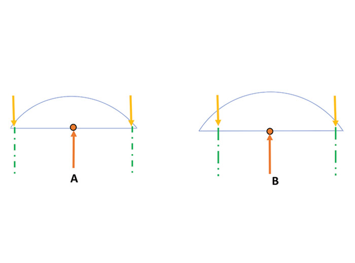
Figure 1
Lens A has a +8.00 front surface and a plano back surface. No decentration is called for, nor is prism needed, and the copper colored dot represents the OC. Lens A is slightly larger than 50 mm in diameter. The OC will be 25 mm from the edge of the finished lens. The broken green lines represent the diameter of the finished lens (50 mm).
Just as the lab was about to edge it, they got a frantic call, saying that the OC was to be decentered in 3 mm. The remake is lens B (for a right eye and seen from above) a bit over a 56 mm diameter, so the distance from the OC to the outer finished edge is 28 mm instead of 25 mm. It is clear that the blank prior to edging is much thicker than the A blank which was done before the request for 3 mm of decentration, the edge finish at the nasal edge will be quite thick. If the lens was thinned to reduce the nasal edge thickness, the diameter would be too small for the eyewire. For the best outcome a frame requiring less decentration should be used.
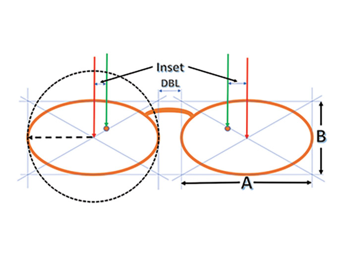
Figure 2
The red arrows point to the geometric centers of each eyewire. The green arrows indicate the MRP locations. The horizontal distance between the red arrow to the green arrow is the decentration, or inward displacement, of the MRP. The Inset in this case is smaller for the right eye, and greater for the left because the monocular PDs are unequal.
The broken-line black circle represents the effective diameter (ED) of the smallest lens blank that can be used to fill the frame.
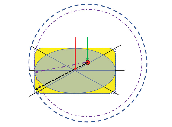
Figure 3
The lens order calls for the MRP (shown as a red dot) to be located 4 mm above the mounting line and decentered inward 6 mm, and the power is – 6.00DS. A rectangular lens shape is shown in yellow. The eye size is 50 mm, and lens blank diameter of about 72 mm will be needed to fill out the eyewire. The broken-line black arrow shows the point at which the lens’ edge will be thickest. The large broken-line circle shows the needed blank diameter. If an oval eyewire shape is used, the minimum blank diameter will be smaller, about 64.5 mm as shown by the dash/dot smaller circle. For the oval shape, the point at which the lens is thickest will be just below the mounting line as indicated by the purple dash/dot arrow. The areas of the yellow lens that is not covered by the oval make up the thickest area of the lens if the rectangular shape is chosen.
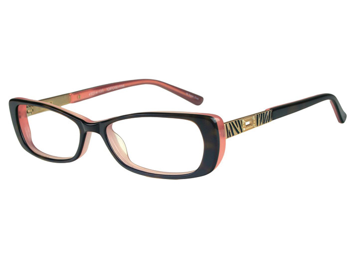
Frame Shape 1
The Day Lily from the Karen Kane Petites selection from Eyewear by ROI has a wide and somewhat thick zyl configuration lateral to the lenses, to give width while limiting the A measurement as well as concealing the edge thickness of minus lens powers.
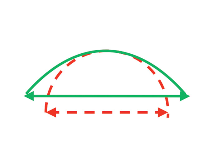
Figure 4
Two plus lenses are shown in cross section. The one outlined in green is aspheric, with its curvature flattening toward the periphery. The other, outlined in red is spherical. Both lenses have the same curvature of their central zones as is shown by the superimposition of one over the other. The maximum diameter that the spherical lens can have is when its diameter is twice its radius as the diagram shows. The aspheric curvature has a significantly greater diameter at a much reduced center thickness because its curve flattens toward the periphery.
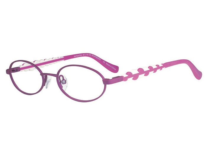
FRAME SHAPE 5A
The narrow oval shape and turnback temples of Fluffy from Eyewear by ROI’s B.U.M. Kids collection is ideal for plus powers. If your lab surfaces for a minimal edge thickness, both weight and magnification will be reduced. The adjustable bridge will allow closer positioning of the OC to the mounting line again saving on weight and magnification.
FRAME SHAPE 5B
This Paisley frame from the COLOURS selection by Alexander Julian from Eyewear by ROI with a rounded shape will reduce the edge thickness of minus lenses and may allow a reduced center thickness of plus lenses. The turnback temple attachment gives width to the front allowing a relatively smaller A measurement of the eyewires. Although the B measurement is fairly deep, the attachment of the temples, approximately a third of the way down from the top of the lenses, means the top of the lenses will swing outward about 33 percent as much as the bottom will swing inward when the pantoscopic angle is increased. If the temple attachments were aligned with the tops of the lenses, 100 percent of the lens movement would be back toward the wearer’s cheeks when panto is added.
MECHANICAL
Excessively thick lenses or steeply curved lenses do not mount as securely in eyewires as thinner or flatter lenses, and thinner plus lenses sometimes must be surfaced thicker to allow the lens to fill the frame (Fig. 1). Weight is another important mechanical factor related to lens thickness. When weight is a primary consideration, the lens volume may be decreased by increasing the index (light bending power) of the lens material, or a lens material of less density can be used. In some situations, a material that combines a lower density with a higher index can be used as a two-pronged approach to reduce lens weight. There is little evidence to guide us in matters of lens weight. For the most part we must rely upon common sense and experience when considering whether a lighter weight lens will be important.
COSMETIC
If a lens is thinner, most lay people believe it appears that they don’t need such a strong prescription, and to a certain extent this is true. The psychology of why needing a weaker lens prescription runs far deeper than Dorothy Parker’s adage that, “Men seldom make passes at girls who wear glasses.” Whether a patient feels thicker lenses gives the appearance of being totally dependent upon the kindness of strangers without them, or perhaps that a “weak-eyesight” flaw exists in his or her gene pool is immaterial and beyond easy logic.
If lens thickness is the patient’s concern, then any reduction in thickness you create must be perceptible to be appreciated. Because there are a number of ways to make lenses thinner, you must select the method(s) of choice carefully.
OPTICS
If you change the optics of the lens that carries the needed prescription to make it thinner, you would not want to do it in such a way that there would be a negative effect on vision. Of course, it is not always easy to predict the outcome when you change the optical characteristics of ophthalmic lenses.
Changing the lens material, the lens size, the lens material or the lens curvatures would have minimal effect on optical performance if your patient only looks through the optical center of the lens. But even if that were possible, there would remain the issues of pupil size, blur sensitivity, occupation and other visual needs that would affect the patient’s response to the optical performance of the new lenses.
Six tools or techniques for making lenses thinner include: reducing the decentration, changing the lens shape, changing the lens curvatures by going to the flatter aspheric designs, using lenticular designs, increasing the index of the lens material or choosing an appropriate frame. Of these six, the one that inexperienced eyewear designers seem to use first and most often is raising the index of the lens material, and it is the technique most likely to cause unexpected post-dispensing optical problems.
RAISING THE INDEX
Useless and annoying reflections created by internally reflected light become brighter as the index of the lens material increases. This effect of higher reflectance can be addressed by using high quality anti-reflective lens treatments.
The other index-related problem, chromatic aberration, tends to be greater when higher index materials are used. Every ophthalmic lens material has an Abbe value which indicates how much the index of refraction differs when considering light of more than a single wavelength. A low Abbe value means that any prism, whether prescribed or encountered by the patient looking away from the optical center, will tend to cause a blur related to Prentice’s Law, shifting the blue wavelengths further from the lens’ center and shifting the longer red wavelengths to a lesser extent. These effects are more troubling for longer viewing distances and when the amount of prism encountered in the periphery is greater.
REDUCING DECENTRATION
Decentration is the distance in millimeters that the MRP (usually the OC of the lens) must be displaced inward horizontally (i.e., toward the nose) from a perpendicular line passing through the geometric center of each eyewire so that the patient’s parallel lines-of-sight can simultaneously pass through the MRPs (Fig. 2). Since a patient’s binocular distance PD is fixed by anatomy, nearly all the options for reducing the amount of decentration rest in selecting the most appropriate frame.
Excessive decentration will tend to make the centers and nasal edges of mid-range and stronger plus prescriptions too thick (Fig. 3). Increased center thickness increases both the weight and magnification of these plus lenses. For strong plus powers the edge thickness can make it difficult or impossible to adjust the nosepads, although the nasal thickness is not so cosmetically noticeable when the glasses are being worn.
The lateral edges of minus lenses become thicker when the decentration is excessive, although this has no effect on center thickness. Myopic patients with prescriptions of about –2.50 diopters or more are often sensitive about the lateral edge thickness of their lenses since it almost “trumpets” the severity of their ocular disability.
A reasonable guideline for decentration is to keep it to no more than 1 to 3 mm in each eye for distance prescriptions. Decentration outward from the geometric center of the eyewear should be avoided. When searching for just the right frame, keep in mind that by adding the eye size and the DBL and dividing by two, you can know immediately whether both monocular PDs fall within the 1 to 3 mm “ideal” decentration. For example, a 50□20 frame would have a 35 mm monocular frame PD, so neither of your patient’s monocular PDs should ideally both fall at more than 34 or less than 32. As with all rules, you can go outside this 1 mm to 3 mm range, but only at the risk of post-dispensing dissatisfaction. The risk is less with lower power prescriptions and becomes exponentially greater with prescriptions above about 3 or 4 diopters or more.
In cases in which the monocular PDs are quite different, and when the lens powers are significant, you may consider subtracting a millimeter or two from the larger monocular PD and add it to the smaller PD, which would be the lens requiring the greater decentration. For example, a distance PD of 36/32 could be ordered 34.5/33.5. This will have the effect of requiring a slight head turn to the right so that the lines-of-sight are moved about 1.5 mm to the left in order for the lines-of-sight to pass simultaneously through the MRPs simultaneously. It also would have the effect of rotating the lens planes approximately 3 degrees clockwise (as seen from above) around a vertical axis.
This PD modification should not be done without the knowledge and written permission of the prescribing doctor. Before requesting this release, it would be a good idea to ask your lab to calculate the minimum and maximum edge thicknesses and the center thicknesses in the case of plus lenses that would result with both the 36/32 PD and the 34.5/33.5 PD, just to be sure you know what will be gained by this change. If the patient has binocular vision, the sum of the monocular PDs must equal the full distance PDs. It would be inappropriate to only modify one of the monocular PDs without compensating the other. Patients should be cautioned that you are making a special modification to reduce lens thickness, and that adaptation may be prolonged by several days as a result.
It is rare that a patient will achieve a good cosmetic outcome if the frame is either wider or narrower than his or her face. Frames with temple attachments that extend outward from the eyewire, (i.e., turnback temples) and bridges with adjustable pads (Fig. 5a and 5b) are the ones that offer the best opportunity for reducing decentration. These designs should be fairly represented among your frame selection.
THE “B” MEASUREMENT
Prior to the advent of PALs, the B measurement (Fig. 1) was not as critical as it is today. Early PAL technology performed better with longer corridors, so a “dueling banjos” sort of marketing took place in which manufacturers advertised minimum fitting heights for their design, each trying for the shortest. The minimum fitting height was more or less recognized as the vertical drop from the Fitting Cross to the center of the Near Reference point. This by definition, cuts off the lower half of the near sweet spot or more depending on the frame design and the patient’s near PD. ECPs quickly found that fitting PALs at the advertised minimum fitting height simply led to trouble. Even with today’s improved PAL technology, many ECPs find it prudent to add 3 mm to any PAL design’s advertised minimum fitting height.
If the lower portion of the lens is not used for vision, and if the frame depth can be minimized without creating an appearance problem (long faces and long noses are cosmetically shortened with longer B measurements), the shorter B measurement will reduce the weight of the lenses. Using a shorter B measurement will not cause either plus or minus lenses to be significantly thinner, but it does decrease lens volume and therefore weight.
LENS SHAPE
The corners of ophthalmic lenses represent little-used areas of most lenses. By using a rounded or oval shape rather than a rectangular shape, the lateral edges of minus lenses appear to be thinner, and the volume of the lenses is reduced. Fig. 3 compares two lens shapes, oval and rectangular. For a –6.00 lens, the edge thickness at the level of the mounting line will be about the same for both shapes, but at the upper and lower lateral corners of the rectangular shaped lens will be quite thick, and for the oval shape, the lateral edges above and below the mounting line will be thinner.
If the lens power in Fig. 3 was +6.00, the arrows indicating the thickest edge of a minus lens would signify the thinnest point of a plus lens. Especially in the case of the rectangular shape, the lab might need to increase the center thickness of the lens in order to have the edge thickness needed to properly finish the lens. Typically, labs will want a minimum edge thickness of around 2.2 mm for grooved mountings and perhaps only 1.4 mm for conventional frames. You should check with your lab, and follow their recommendations if in doubt about higher plus powers in mountings that require grooving because this will change the center thickness, magnification and appearance of the finished eyewear.
ASPHERIC CURVATURES
Prior to the development of implants, the use of aspheric lenses was one of the most significant improvements in bringing clear, more comfortable vision to aphakic patients. These lenses (around +12.00) were lighter in weight and gave a wider field of view than any other design of similar high plus power. A decade or so later the technology was expanded to permit wearers of lower power plus lenses and even minus lenses to have some of the advantages of the aspheric designs.
FULL FIELD ASPHERICS
The cross section of an aspheric lens shown in Fig. 4 clearly demonstrates that the peripheral curvature is flatter than the central curvature. The rate of flattening from the center to the periphery can be adjusted to correct for power error and marginal astigmatism, and this allows the patient to experience the correct prescription power from the central area to the periphery. The result is a wider field of view and a reduced thickness. Full field aspherics are available in both plus and minus powers.
LENTICULAR ASPHERICS
With very strong lens powers, it is not possible to achieve sufficient flattening for good appearance and weight reduction and at the same time provide adequate correction of the peripheral aberrations of marginal astigmatism and power error. Modern aspheric lenticular lenses, just like the old “fried egg” lenticular design have two distinct zones. The part of the lens in the center is usable for vision. It is called the aperture. The zone between the aperture and the frame is called the carrier, and generally does little or nothing to correct the patient’s defocus. Check with your lab for availability and recommendations when considering lenticular aspheric lenses, especially for presbyopes.
Aspheric curves allow you to design lighter weight lenses, and their flatter peripheral curves permit the lenses to be mounted more securely in standard frames. Aspheric curves also reduce edge thickness for minus prescriptions, an advantage myopic patients certainly appreciate. For plus prescriptions, excessive center thickness causes unsightly magnification, and this is reduced when aspheric curves are used.
Modern aspheric lenses are almost universally atoric, which means that peripheral aberrations are reduced in the periphery in both Major Meridians, which gives a larger and more rounded sweet spot. The older, more steeply curved Corrected Curve lenses could only correct for peripheral aberrations in the sphere-powered meridian, and the result was that the sweet spot was oval in shape. For example, a plano -4.00 x 090 lens would have a base curve that was correct for the vertical meridian, but too flat for the horizontal meridian, which is the meridian in which we most use the periphery of our lenses for distance seeing. Astigmatic patients may be good candidates for atoric lenses starting as low as two diopters of cylinder.
KNOWING YOUR OUTCOMES IN ADVANCE
Your lab knows that you need to dispense patient-pleasing eyewear, and they can give you answers if you are undecided about a frame choice or a lens design. If your patient has a -7.75 -2.00 x 030 Rx, and you want to know just how thick the lateral edge of the lens will be if you use either one or another frame, they can do a “calc” (i.e., calculation) if they know the frame’s name, eye size, bridge size, the patient’s monocular PDs, and the lens material and design. They can also give you comparative information if you want to compare one material to another before you make your design decision. For plus prescriptions, they can give you a calc to determine the center thickness and the location and amount of the maximum edge thickness for plus lenses.
If you request this service, remember that labs are very busy places, and these calculations not only take time, they can be disruptive to the normal work flow—your work along with all the other ECPs who use the same lab can be affected. Many labs will give a courtesy calc occasionally, but it is a valuable service, and you should inquire about the cost of the service if you expect to use it.
REFINE YOUR OWN LEARNING CURVE
Designing patient-pleasing eyewear is both an art and a science. If you rely only on patients’ complaints, the growth of your learning curve will be both skewed and stunted. Dentists and surgeons frequently call their patients after care has been provided. They want to proactively learn about their outcomes, and they want their patients to understand the care that was provided. If there are issues related to that care, they want to hear about them and provide possible solutions. It is human nature for people to discuss issues, difficulties and disasters to all who will listen in preference to positive events in their lives. It is better for you learn about patient concerns, because if you don’t, the friends, relatives and coworkers of the patient will certainly hear those concerns, and the problems will go unabated.
When dispensing special design lenses, especially those in the higher power ranges, prepare your patient for adaptation. Patients can adapt to poorly designed lenses, and when they first receive new eyewear of a better design, the adaptation may at first seem daunting. Your prior explanation and encouragement can serve them well. A phone call a few days after dispensing by you or a staff member can build your reputation as a health care provider, screen out possible errors, omissions and misunderstandings, and foster the growth of your practice. It’s also an opportunity to learn how appreciative people can be of your care. ■
TERMINOLOGY AND HELPFUL DEFINITIONS
A, B AND DBL—These are the designations given to the width (A), depth (B) and the shortest separation (DBL) of lenses measured by the Boxing System.
BOXING SYSTEM—This is a method of measuring the dimensions of ophthalmic lenses by using a horizontal rectangle with horizontal and vertical contours that are tangent to the lens edges. Once the lens has been “boxed,” diagonal lines joining the corners of the box will cross at the geometric center of the lens (Fig. 2)
CORRECTED CURVE—Corrected curves are spherical curvatures designed to correct aberrations when viewing peripherally or away from the optical center. Until the development of digital surfacing equipment, it was only practical to produce most lenses with spherical curves. Corrected curve lenses tend to be significantly thicker and more steeply curved than aspheric lenses. Spherical curves have only one radius of curvature, and aspheric curve have radii of curvature that vary in length (Fig. 4).
MAJOR MERIDIANS—The meridians are numbered in 1 degree increments from 001 (1 degree counterclockwise from horizontal) to 180. The meridian with the most plus or least minus power, and the meridian with the least plus or most minus power are termed the Major Meridians, and the axis of the patient’s cylinder will be in one of the Major Meridians depending on whether the prescription is written in plus or minus cylinder form.
MAJOR REFERENCE POINT—The Major Reference Point (or MRP) of an ophthalmic lens is the one point in the lens that gives exactly the desired prescription.
OPTICAL CENTER—The optical center (or OC) of a lens with optical power is the one point through which a ray of light will pass without being deviated.
PRENTICE’S LAW—This law, or rule, states that a light ray passing at a given distance from the optical center of a lens will be deviated by a prism effect in prism diopters that is equal to the power of the lens in diopters times the distance (in centimeters) to the optical center. The base of the prism will be toward the optical center for plus powers and away from the optical center for minus powers. For lenses with cylinder, the power in the meridian defined by a line from the ray’s intersection with the lens to the optical center is used for the calculation.
PRISM DIOPTER—A prism diopter is a unit of measurement that gives the deviation of light by a prism. One centimeter of deviation at a distance of one meter would be one prism diopter (1△).
SWEET SPOT—The sweet spot of an ophthalmic lens is the area surrounding the MRP throughout which the patient experiences lens performance that is no less than the performance through the MRP or point of best lens performance. The size of the sweet spot tends to increase during adaptation, and it can be dependent on lighting, atmospheric conditions, pupil size and other factors.
Contributing editor Palmer R. Cook, OD, is an optometric educator and optical dispensing expert.